
My Masters of Science Thesis involved the usage of a so-called "omnidirectional camera". There are various ways of achieving 180° or even 360° view, with their distinct pros and cons. The general benefit of these alternative camera systems is that objects don't need to be tracked, because generally they stay withing the extremely broad Field of View (FoV) of the camera. This is also very beneficial in visual odometry tasks, because landmarks can be tracked for longer periods of time.
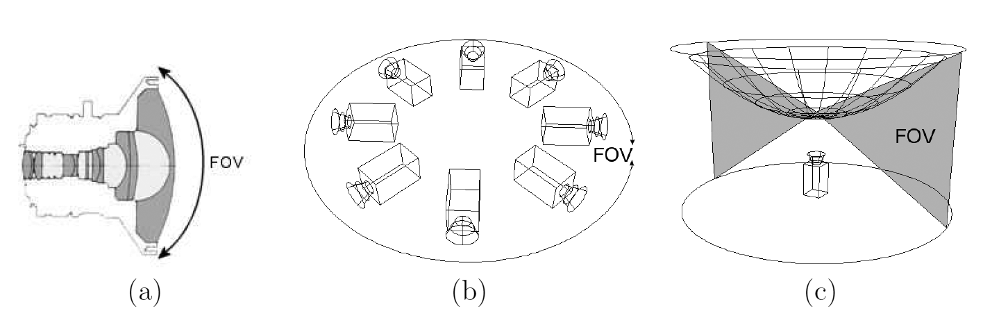
Some design options are shown in Figure 1. The simplest solution is to use a fish-eye lens, and it is fairly straight forward to calibrate. However the image resolution is typically somewhat limited, and it cannot cover much more than 180°. An alternative approach is to use multiple normal cameras, an combine their images in software. This can produce very high resolution images, but requires a lot more effort and parameters in calibration, especially since also vingetting needs to be corrected before images can be joined seamlessly together. There are commercial products such as Ladybug from PointGrey. The third option is to use a combination of a traditional lens and a concave mirror to achieve up to 360° × 90° FoV. These are relatively compact and mid-priced, with a bit limited resolution and a fairly simple calibration models and procedures. This is the type of camera system I used at my Master's Thesis, which was titled Real Time Feature Tracking on Omnidirectional Camera Image in Forest Environment.
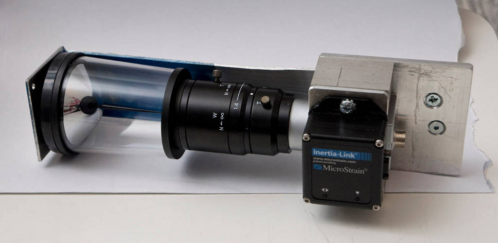
The camera system I used in my thesis is presented in Figure 2. In addition to the omnidirectional camera system, it has an Inertial Measurement Unit (IMU) and a supporting structure to attach an compact 2D laser scanner (40 × 40 mm) such as Hokuyo URG. This leaves us with a FoV of about 290°, which is not an problem because typically part of FoV would be blocked by the user or robot anyway. Anyway this dark area can be ignored during image rectification.
One intuitive image rectification model is to make each image pixel correspond to an equal solid angle. For example if the camera has a FoV of 360° × 90°, suitable image resolutions would have resolutions such as 360 × 90 and 720 × 180. To determine the actual mapping, the camera must be calibrated.
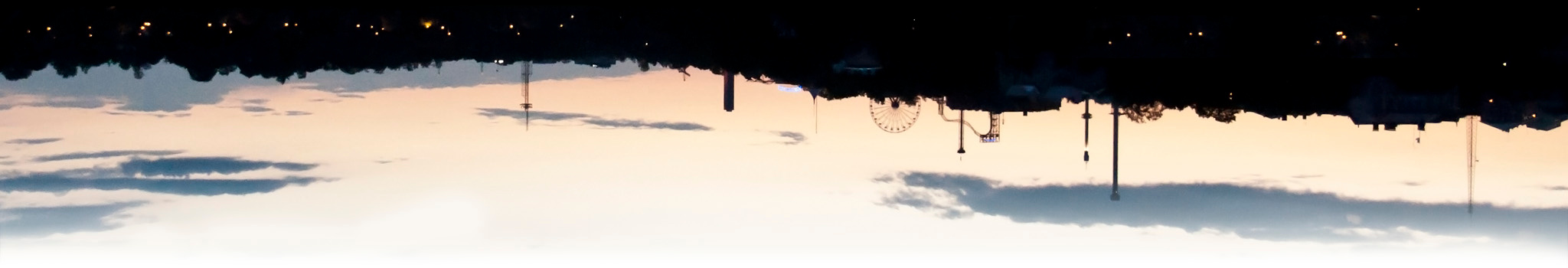
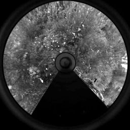
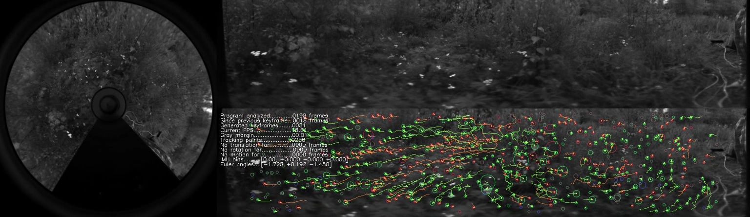
An example captured frame can be seen in Figure 3. The captured image on the right, and the converted panorama is on top-right. The bottom-right image is overlayed with interest points and their tracks, and some metadata about the program's frame rate etc. This was generated by the program I developed for my Master's Thesis, which I'll describe in an other article.
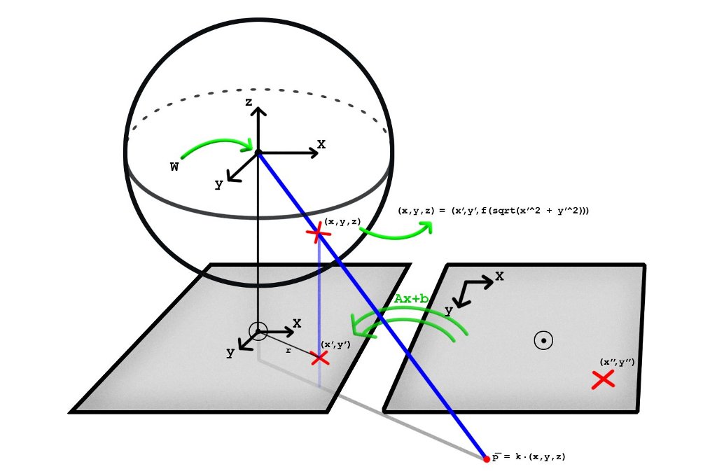
One simple model was presented in [1], which is based on a kind of an radial basis function to determine the z-component of the light ray (when camera is looking at the z-direction). This is illustrated in Figure 4, and other illustrations can be seen in the original paper. In this model it is very easy to determine the light ray's direction for each pixel, but it is more difficult to calculate the object's location on the image based on its position in relation to the camera.
Let's first revise how the typical perspective camera is parametrized. The linear pinhole camera model is well described in Wikipedia. It is important to differentiate between intrinsic and extrinsic parameters. Basically intrinsic parameters describe the physical aspects of the camera and lens, such as focal length and pixel density. Extrinsic parameters describe the location and orientation of the camera in world coordinates. To determine object's location in the image, first extrinsic parameters are used to determine object's location in camera's coordinate system. Then intrinsic parameters are used to project the object to the camera's sensor plane. To determine that which direction a given pixel is observing, these steps are applied in reverse order. This model cannot account for lens distortion, nor it models vignetting.
This same model cannot be applied to omnidirectional cameras, because it operates on a fundamentally different principle. Interestingly the more generic model can be used to describe any camera with a single viewpoint property, including perspective cameras. For these it is also able to account for lens distortion.
Starting from a point on the image, it is first transformed via affine transformation into a new coordinate system, in which the origin is close to the image center. This is essentially the same parametrization as in the pinhole camera model. Then the pixel's distance from the new origin is determined, and it is used to evaluate a low-degree polynomial function to determine the z-component of the ray. Usually the polynomial needs to have a higher degree than two, but not really greater than four.
If the camera is also able to see ''behind'' it, then this polynomial will get also negative values. For an ideal pinhole camera this function would just have constant value, which corresponds to the focal length of the lens (in pixel units). When lens distortion is present, it will either grow (for barrel distortion) or decrease (for pincushion distoriton) as the pixels are further away from the center. Nevertheless for normal lenses it will not deviate that much from its value at the origin. There can be greater changes for fisheye lenses.
For the used omnidirectional system this function started from a big positive value, reached 0 at a distance of \textasciitilde 500 pixels and grows to positive after that. This means that pixels near the image center are actually gathering light behind the camera, or in case the camera is pointed upwards, these pixels are seeing the ground. Correspondingly pixels near the image border are gathering light above the horizon.
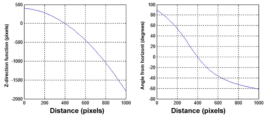
To use this calibration data for generating a panoramic image in which each pixel covers the equal solid angle, this mapping function needs to be used to determine the azimuth angle for each pixel distance. This is calculated as α(r) = arctan(f(r)⁄r), which clearly does not have a closed form solution. The relationship between f(r) and α(r) can be seen in Figure 5 for f(r) = 400 - 0.2 r - 0.002 r2.
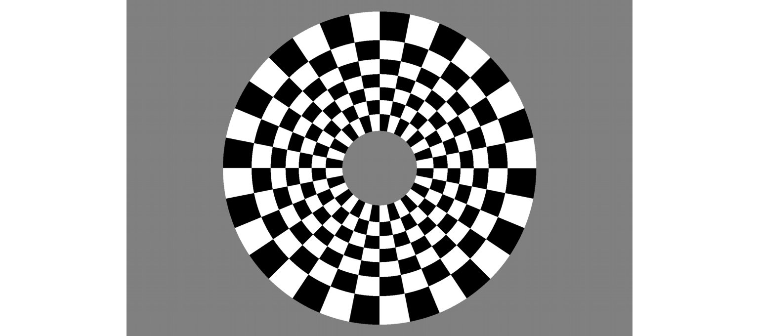
To sample images from 65° to -40° at 15° intervals, the corresponding distances from the image center are roughly 150, 220, 280, 330, 380, 440, 520 and 630 pixels. The resulting pixel sampling pattern is shown in Figure 6, with 24 samples along the horizontal angle.
| 1 | D. Scaramuzza, A. Martinelli, R. Siegwart A flexible technique for accurate omnidirectional camera calibration and structure from motion Proceedings of IEEE ICVS, 2006. PDF |
Related blog posts:
|
|
|
|
|
|
|
|
|
|
